High-Performance, high reliable and high-safety Li-Ion rechargeable battery for offshore subsea electronics. Designed for deployments up to 25 years, the electronic and Li-Ion cells are extreme robust and fail-safe.

High-Performance, high reliable and high-safety Li-Ion rechargeable battery for offshore subsea electronics. Designed for deployments up to 25 years, the electronic and Li-Ion cells are extreme robust and fail-safe.


Manufacturing according to ISO 13628-6 & API17F
Qualified systems for international Airfreight (IATA)

Military Standard – shock & vibration tested

Developed according to the requirements of functional safety
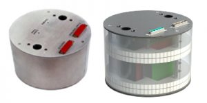
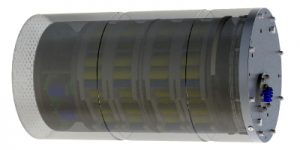
Subsea 14V Li-Ion Battery with ISO ROV switch
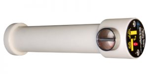
The battery has a 14 V output that can deliver 7A without time limit. Loading is only top-side. With an energy of 674Wh, the battery can be used flexibly. The ROV Low-torque rotary switch follows ISO 13628-8:2002-12 (E).
| Charge voltage: | Top-side only |
| Output voltage: | nominal 14.4V |
| Nominal energy: | 674Wh |
| Max. current: | 7A |
| Diagnostic: | No |
| Battery: | Li-Ion |
| Design life: | 25 year |
| Batt. Life time: | 10 years minimum |
| Housing: | Titanium battery housing - POM ROV switch |
| Operating depth: | 2000m, test at 330 Bar |
| Operating temp.: | -20 …+55°C |
| Charge temp.: | 0 …+45°C (never charge below 0°C) |
| Storage: | -20 …+60°C (recommended: +5 …+20°C) Store at 50..80% SOC, recharge 3...6 months |
| Data interface: | No |
| ROV Switch: | Rotary low-torque ISO 13628-8:2002-12 75Nm switch |
| Control light: | Red if off, no light if running (other on request) |
| Qualification: | Offshore filed approved since 2013 UN T38.3 |
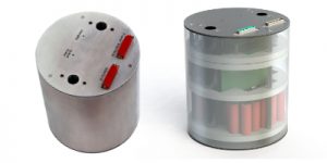
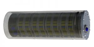
Subsea Li-Ion Battery 14V sec. Li-Ion Battery
The battery has a 14 V output that can deliver 7A continuously and is charged topside. With an energy of 674Wh, the battery can be used flexibly. Optional ROV low-torque rotary switch according ISO 13628-8:2002-12 (E) available
| Charge Voltage: | Top-side only |
| Output voltage: | nominal 14.4V |
| Nominal energy: | 674Wh |
| Max. current: | 7A |
| Diagnostic: | No |
| Battery: | Li-Ion |
| Design life: | 25 year |
| Batt. Life time: | 10 years minimum |
| Housing: | Titanium battery housing |
| Operating depth: | 2000m, test at 330 Bar |
| Size: | Battery: Ø90 mm, length mm (w/o conn.) |
| Weight: | 9kg approx.. |
| Operating temp.: | -20 …+55°C |
| Charge temp.: | 0 …+45°C (never charge below 0°C) |
| Storage: | -20 …+60°C (recommended: +5 …+20°C) - Store at 50..80% SOC, recharge 3...6 months |
| Connector: | SubConn® BH4-F |
| Data interface: | No |
| ROV Switch: | Optional:Rotary low-torque 75Nm switch |
| Control light: | Optional with ROV switch |
| Qualification: | Offshore filed approved since 2013 UN T38.3 |
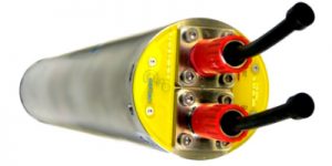
Subsea-UPS Li-Ion 24V 63Wh
The battery has a 24V input and a regulated 24V output. The output current is limited to 4A for 120sec.
| Input / charge: | 24V |
| Input current: | 1A charging + 4A output peak |
| Output Voltage: | 24.V |
| Output current: | 4A |
| Battery: | 28.8V, 63.3Wh |
| Life-time: | 10 years min., up to 25 years with diagnostic |
| Diagnostic: | Automatic test once per week Without disturbing the main function |
| Buffer time: | 120s set by hardware |
| Auto recharge: | 4-5 days |
| Design life: | 25 year |
| Batt. Life time: | 10 years minimum |
| Size: | Ø 184 mm, height 127 mm (w/o conn.) |
| Operating temp.: | -20 …+55°C (cell temp. max. +60°C) |
| Charge temp.: | 0 …+45°C (never charge below 0°C) |
| Storage: | -20 …+50°C (recommended: +5 …+20°C) - Store at 50..80% SOC, recharge 3...6 months |
| Data interface: | RS-485 MODBUS, isolated, Modicon PI-MBUS-300 |
| Qualification: | GS EP SPS 022 Rev.02 S+V (ISO 13628-6), GL VI 7-2 (EMC, conducted and radiated) Comparable to API17F |
Subsea-UPS Li-Ion 24V 253Wh 70W
The battery has a 24V input and a regulated 24V output. The output current is limited to 3A / 70W, without time limit With an energy of 253Wh, the battery can be used flexibly.
| Input Voltage: | 24V |
| Input current: | 1A charging + 3A output |
| Output Voltage: | 24V regulated |
| Output current: | 3A, max. 70W |
| Battery: | Li-Ion nominal 28.8V, 300Wh, Used: 253Wh |
| Recharge: | automatically 3-4 days |
| Buffer time: | 60min |
| Diagnostic: | Automatic test once per week - Without disturbing the main function |
| Data interface: | MODBUS RTU, Modicon PI-MBUS-300 |
| Design life: | 25 years |
| Batt. Life time: | 10 years minimum |
| Size: | Ø 184 mm, height <220 mm (w/o conn.) |
| Operating temp.: | -20 …+55°C (cell temp. max. +60°C) |
| Charge temp.: | 0 …+45°C (never charge below 0°C) |
| Storage: | -20 …+50°C (recommended: +5 …+20°C) - Store at 50..80% SOC, recharge 3...6 months |
| Qualification: | API17F |
Subsea-UPS 400V High-Energy 4.3kWh
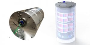
High-energy subsea 400V DC online UPS battery with low power 400V DC charge input, 400V DC 1kW output and additional aux. 24V DC output, with optional higher 400V output current. Buffer time 1hour @1kW. Fully qualified according API17F and with transport test UN T38.3
| UPS type: | online UPS |
| Output: | 400V - Optional 187V battery not regulated |
| Output power: | 1000W, 1600W peak 1min. - Optional 2000W |
| Input / charge: | 400V max. 1.5A / 600W |
| Battery: | Li-Ion Nominal 187.2V 23Ah |
| Nominal energy: | 4.3kWh |
| Aux. output: | 24V 240W |
| Self-discharge: | < 5% per year at +25°C |
| Redundancy: | No |
| Data interface: | MODBUS RTU, Modicon PI-MBUS-300 - Optional: CAN/FT - On request: CANopen safety acc. EN 50325-5, CIA 305 |
| Diagnostic: | No. Optional available. |
| Housing: | OEM or SEM housing |
| Size: | Ø298mm x 550mm -2.5mm ( w/o connector) - w/o SEM: Ø258mm x 455mm length |
| Weight: | 67kg - w/o SEM: 33.5kg |
| Connector: | GISMA penetrator, other on request |
| Operating temp.: | -20 …+55°C (cell temp. max. +60°C) |
| Charge temp.: | -5 …+45°C (recommended: > 0°C) |
| Storage: | -20 …+50°C (recommended: +5 …+20°C) - Store at 50..80% SOC, recharge 3...6 months |
| Design life: | 25 years |
| Batt. Life time: | 10 years minimum |
| Qualification: | API17F - UN T38.3 |
Subsea-UPS 200V 1.7kWh LP-6.5kW LFP
High-power subsea 200V DC UPS battery with low power 200V DC charge input, 200V DC 6.5kW output, with optional higher current. Cycles defined for 45s, 3 cycles every 4 hours. Fully qualified according API17F and with transport test UN T38.3
| UPS type: | online UPS |
| Input / charge: | 200V, 2 x 100W |
| Aux. input: | 24V |
| Output: | 200V |
| Power: | 6500W 45s, 3cycles, every 4h |
| Battery: | LFP nominal 184V |
| Nominal energy: | 1.7kWh (2 channels 850Wh each) |
| Self-discharge: | < 5% per year at +25°C, lower subsea |
| Data interface: | RS-485 galvanic isolated MODBUS RTU Optional: CAN/FT, CANopen safety acc. EN 50325-5, CIA 305 |
| Housing: | OEM or SEM housing |
| Size: | Ø298mm x 550mm ( w/o connector) w/o SEM: Ø258mm x 455mm length |
| Weight: | 62kg (approx..) w/o SEM: 33.5kg (TBD) |
| Connector: | GISMA penetrator, other on request |
| Operating temp.: | -30 …+55°C (cell temp. max. +60°C) API17F Q1 Test -18… +70 |
| Storage: | -40 …+60°C (recommended: +5 …+20°C) Store at 50..80% SOC, recharge 3...6 months |
| Design life: | 25 years |
| Batt. Life time: | 10 years minimum |
| Qualification: | API17F |
Subsea-UPS 400V 1.7kWh LP-6.5kW LFP
High-power subsea 400V DC UPS battery with low power 400V DC charge input, 400V DC 6.5kW output, with optional higher current. Cycles defined for 45s, 3 cycles every 4 hours. Fully qualified according API17F and with transport test UN T38.3
| Input / charge: | 400V, 200W |
| Aux. input: | 24V (9…36V) |
| Output: | 400V (nominal 370V unregulated battery output) |
| Power: | 6500W 45s, 3cycles, every 4h |
| Battery: | LFP nominal 392V, 1 single channel (module) |
| Nominal energy: | 1.7kWh |
| Self-discharge: | < 5% per year at +25°C, lower subsea |
| Redundancy: | No, but UPS can be connected in |
| Data interface: | MODBUS RTU, Modicon PI-MBUS-300 - Optional: CAN/FT - On request: CANopen safety acc. EN 50325-5, CIA 305 |
| Housing: | OEM or SEM housing |
| Size: | Ø298mm x 550mm ( w/o connector) - w/o SEM: Ø258mm x 455mm length |
| Weight: | 62kg (approx..) - w/o SEM: 33.5kg (TBD) |
| Connector: | GISMA penetrator, other on request |
| Operating temp.: | -30 …+55°C (cell temp. max. +60°C) - API17F Q1 Test -18… +70°C |
| Storage: | -40 …+60°C (recommended: +5 …+20°C) - Store at 50..80% SOC, recharge 3...6 months |
| Design life: | 25 years |
| Batt. Life time: | 10 years minimum |
| Qualification: | API17F |
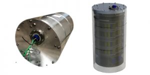
Subsea-UPS 200V 3.4 kWh HP-15kW LFP
High-power subsea 200V DC UPS battery with low power 200V DC charge input, 200V DC 15kW output, with optional higher current. Cycles defined for 45s, 3 cycles every 4 hours. Fully qualified according API17F and with transport test UN T38.3
| Input / charge: | 200V, 2x300W |
| Aux. input: | 24V (9…36V) |
| Output: | 200V (nominal 184V unregulated battery output) |
| Power: | 15000W 45s, 3cycles, every 4h |
| Battery: | LFP nominal 184V, 2 channels (modules) |
| Nominal energy: | 3.4kWh (2 channels 1.7kWh each) |
| Self-discharge: | < 5% per year at +25°C, lower subsea |
| Redundancy: | Yes, 2 channels |
| Data interface: | MODBUS RTU, Modicon PI-MBUS-300 - Optional: CAN/FT - On request: CANopen safety acc. EN 50325-5, CIA 305 |
| Housing: | OEM or SEM housing |
| Size: | Ø298mm x 850mm ( w/o connector) - w/o SEM: Ø258mm x 755mm length |
| Weight: | 92kg (approx..) - w/o SEM: 50kg (TBD) |
| Connector: | GISMA penetrator, other on request |
| Operating temp.: | -30 …+55°C (cell temp. max. +60°C) - API17F Q1 Test -18… +70°C |
| Storage: | -40 …+60°C (recommended: +5 …+20°C) - Store at 50..80% SOC, recharge 3...6 months |
| Design life: | 25 years |
| Batt. Life time: | 10 years minimum |
| Qualification: | API17F |
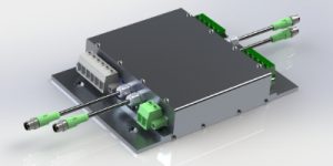
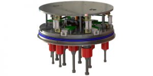
Energy Storage System
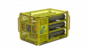
Power & Switch Unit PDU MOSFET 100V 100A
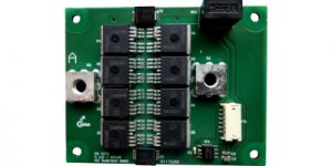
System integration: PDU Units
System integration of PDU into junction box